
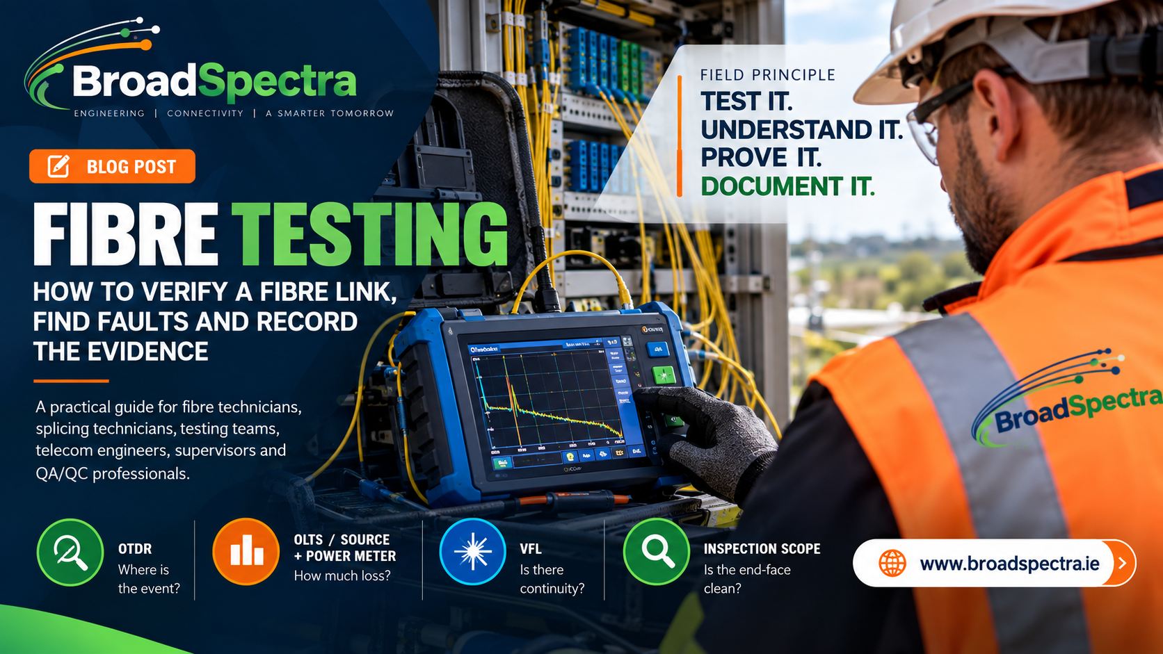
Fibre Testing: How to Verify a Fibre Link, Find Faults and Record the Evidence
A practical guide for fibre technicians, splicing technicians, testing teams, telecom engineers, supervisors and QA/QC professionals.
FIELD PRINCIPLE: TEST IT. UNDERSTAND IT. PROVE IT. DOCUMENT IT.
A fibre link can appear to be installed correctly and still fail to meet the required performance. That is why fibre testing is more than a final inspection exercise. It helps technicians verify network performance, identify faults, investigate unexpected results and create the technical evidence needed for project acceptance and future maintenance.
Whether you are commissioning a new fibre link, checking completed installation work, troubleshooting a fault or preparing a project handover, a structured testing process is essential.
At BroadSpectra, our engineering philosophy is straightforward: a working fibre link is the objective; a verified, traceable and digitally documented network asset is the standard.
1. Why Is Fibre Testing Important?
Fibre optic networks support broadband connectivity, business communications and critical digital infrastructure. To perform reliably, installed links must be tested against the relevant project requirements.
Fibre testing can help determine whether:
- The correct fibre has been identified and connected.
- Optical loss falls within the required acceptance limits.
- Connectors are clean and free from visible damage.
- Splices and other events require further investigation.
- A fibre link has continuity.
- An unexpected loss, reflection or interruption may be present.
- The completed installation has sufficient test evidence for handover.
Testing should never be treated as a formality. It is an essential part of quality assurance, commissioning and network maintenance.
The objective is not simply to obtain a test result. It is to understand what the result tells us about the network.
IMPORTANT: Testing methods, wavelengths, acceptance limits, reference procedures and safety controls must follow the project specification, applicable standards and equipment manufacturer's instructions.
2. Choosing the Right Fibre Testing Equipment
Different testing instruments answer different questions. Selecting the right tool helps technicians investigate the network efficiently and avoid drawing conclusions from incomplete evidence.
Optical Time-Domain Reflectometer (OTDR)
An OTDR helps technicians investigate events along a fibre link.
It can assist with:
- Locating events and estimating their distance.
- Examining attenuation and reflections.
- Investigating unexpected loss.
- Supporting commissioning and troubleshooting.
- Saving trace records for technical review.
An OTDR trace requires competent interpretation. Automated settings do not remove the need for engineering judgement.
An OTDR should also not be treated as a replacement for end-to-end insertion-loss testing.
Optical Light Source and Power Meter
An optical light source and power meter can be used to measure end-to-end insertion loss when the appropriate reference procedure is followed.
These measurements help technicians assess how much optical signal is lost across the link.
Optical Loss Test Set (OLTS)
An OLTS is used for end-to-end insertion-loss testing. The measured result should be compared with the project's calculated loss budget and acceptance criteria, where applicable.
Visual Fault Locator (VFL)
A VFL provides a visible indication of continuity or certain faults over a suitable short section of fibre. Its use depends on the fibre, access conditions and test requirements.
Fibre Inspection Scope
An inspection scope helps technicians examine connector end-faces for contamination or damage before making a connection or measurement.
Launch and Receive Fibres
Launch and receive fibres help characterise the OTDR measurement at the beginning and end of a fibre link, where required by the test method.
The key principle is simple: choose the test method that answers the engineering question.
3. Before You Start Testing: Prepare the Link
Good test results begin before the testing equipment is connected.
A technician should first establish exactly which fibre is being tested and confirm that the measurement setup is appropriate.
The pre-test checklist
Before testing:
- Confirm the correct cable, buffer or tube, fibre identification and destination.
- Check the cable schedule, splice schedule, ODF schedule and relevant drawings.
- Confirm the test direction and required wavelengths.
- Understand the project's acceptance criteria.
- Check the condition and calibration status of the test equipment, as applicable.
- Inspect the connectors that will form part of the measurement path.
- Clean optical interfaces using approved fibre-cleaning materials.
- Re-inspect the connectors after cleaning.
- Confirm the reference method and check launch/receive fibres where required.
- Prepare the digital test record using the correct project naming convention.
These checks help reduce avoidable testing errors and make the resulting evidence easier to trace.
FIELD TIP
Identify the fibre before you test it. A technically correct result attached to the wrong fibre or asset can still create serious problems during handover and future maintenance.
4. The Fibre Testing Procedure: Step by Step
A consistent procedure helps technicians work systematically and ensures that the evidence collected can be understood by supervisors, engineers and quality teams.
Step 1 — Identify the fibre
Confirm the complete path:
Cable → Buffer/Tube → Fibre → Destination
Cross-check the cable and fibre identification against the approved schedules and drawings before connecting the equipment.
Step 2 — Inspect the connectors
Inspect each connector that forms part of the measurement path.
Look for:
- Dirt and contamination.
- Scratches or cracks.
- Physical damage.
- Other visible defects that may affect the measurement.
Step 3 — Clean and re-inspect
Use approved fibre-cleaning materials and procedures.
After cleaning, inspect the connector again. Do not assume that an optical interface is clean simply because it has been wiped.
Step 4 — Verify continuity
Use an appropriate method for the task, such as a VFL, fibre identifier or source-and-meter approach.
Follow the approved test procedure and equipment instructions.
Step 5 — Perform optical loss testing
Use an optical light source and power meter or an OLTS to measure end-to-end insertion loss.
Record the relevant test wavelength, reference method, equipment and measured result.
Compare the result against the applicable project acceptance criteria.
Step 6 — Perform OTDR testing
Where required, configure the OTDR for the fibre and task.
The settings may include:
- Wavelength.
- Measurement range.
- Pulse width.
- Averaging.
- Launch and receive fibres.
The configuration should be appropriate to the fibre plant and the purpose of the measurement.
Step 7 — Analyse the OTDR trace
Review the trace for connectors, splices, reflections, attenuation, bends, unexpected losses and the fibre end.
Do not rely solely on an automated pass indication or the visual appearance of the trace. Interpret the evidence using competent engineering judgement.
Step 8 — Test from the opposite end where required
A measurement from the opposite direction can strengthen event and splice-loss assessment when required by the project procedure.
Step 9 — Compare the results with acceptance criteria
The question is not simply whether the trace looks good.
The technician must determine whether the measured results meet the project's requirements and the applicable loss budget.
Step 10 — Investigate failures
If a result fails, investigate the cause, correct the problem and retest.
Never hide, relabel or discard an unacceptable result to make the installation appear compliant.
Step 11 — Save the test evidence
Record the project, site, cable, fibre, test direction, wavelength, equipment, technician, date and result.
Step 12 — Digitally archive the record
Link the test evidence to the relevant physical asset, location, drawing, photograph and handover record.
This makes the information easier to retrieve when the network requires maintenance or fault investigation.
The complete procedure follows the principle of identifying, inspecting, cleaning, testing, analysing, verifying and documenting the link.
5. How Should Technicians Respond to Failed Test Results?
A failed test should trigger an investigation—not guesswork.
The first observation can guide the next check, but the technician should confirm the cause before deciding on corrective action.
| Observation | Possible cause | Practical response |
| High loss | Dirty connector, poor splice or bend | Inspect and clean connectors; investigate the physical path and splice points; correct and retest. |
| Unexpected reflection | Connector, mechanical event or damaged point | Inspect relevant interfaces and use appropriate measurements to investigate the event. |
| Unexpected distance | Incorrect fibre identification, route information or OTDR settings | Verify the fibre identity, route and instrument parameters before interpreting the distance. |
| No continuity | Break, wrong patch or incorrect fibre | Trace the path, verify identification, locate the interruption, rectify and retest. |
These are possible causes, not automatic diagnoses. The technician must use the available evidence and the approved troubleshooting procedure to establish what has happened.
The correct response to a failed test
FAIL → INVESTIGATE → RECTIFY → RETEST → RECORD
A repair is not complete simply because the suspected defect has been corrected. The required tests must be repeated to verify the result.
6. Digital Documentation: Every Test Needs a Record
Fibre testing produces valuable technical information. However, that information becomes much more useful when it is saved, correctly identified and linked to the relevant network asset.
Without reliable documentation, a future technician may struggle to determine which fibre was tested, where the measurement was taken or whether the link previously met its acceptance criteria.
A digital test record should capture:
- Project name and site/location.
- Cable identification.
- Buffer or tube identification.
- Fibre identification.
- Test direction and wavelength.
- OTDR identification, where applicable.
- Power meter or OLTS identification, where applicable.
- Technician name.
- Date and time.
- Reference method.
- Measured result and acceptance status.
- Original trace or test file.
- Relevant asset location, drawing and photograph.
- Handover record or other applicable project reference.
The original test evidence should be retained according to the project requirements and document-control procedures.
Why does this matter?
Good digital documentation supports:
- Project acceptance and quality assurance.
- More efficient technical reviews.
- Traceable handover information.
- Future fault investigation.
- Network maintenance and restoration.
- Better understanding of the installed infrastructure.
At BroadSpectra, digital documentation is part of the engineering workflow—not an administrative task to be completed after the technical work has been forgotten.
The principle: know what was installed, know what was tested and preserve the evidence.
7. Fibre Safety: Never Skip the Basics
Fibre testing must be performed with appropriate safety controls.
Technicians should:
- Treat every fibre as potentially live.
- Never look directly into a fibre or connector.
- Wear appropriate eye protection.
- Control fibre shards and dispose of scraps correctly.
- Follow site safety procedures.
- Follow equipment manufacturer's instructions.
- Stop and escalate when an unsafe or unexpected condition arises.
Safety is part of engineering quality. A technically successful test does not justify an unsafe working method.
8. A Quick Fibre Testing Checklist
Before closing a testing activity, confirm that:
☐ The correct fibre was identified against the approved schedules and drawings.
☐ Connectors were inspected and cleaned before connection.
☐ Test equipment was checked and suitable for the task.
☐ The reference method was confirmed.
☐ The correct wavelength was selected.
☐ OTDR parameters were verified where OTDR testing was required.
☐ The required loss and trace tests were completed.
☐ Results were reviewed against the applicable acceptance criteria.
☐ Failed results were investigated, corrected and retested.
☐ Original test evidence was saved and digitally linked to the asset.
A completed checklist supports the process, but it does not replace the actual test results or the technical review required by the project.
9. Ten Golden Rules for Fibre Testing
At BroadSpectra, we believe that good engineering is built on disciplined field practice.
Keep these ten rules in mind:
01. Identify before you test.
02. Inspect before you connect.
03. Clean before you measure.
04. Use the right test for the question.
05. Don't trust a trace you don't understand.
06. Compare results with acceptance criteria.
07. Failures require investigation.
08. Save the original test evidence.
09. Link test results to the physical asset.
10. Document today for the engineer who needs it tomorrow.
These principles help technicians produce results that can be understood, verified and used throughout the network lifecycle.
10. From Fibre Installation to a Verified Network Asset
Fibre engineering does not end when the cable has been installed or the splice closure has been closed.
The complete process connects physical work with technical verification and reliable project records.
The BroadSpectra Engineering Principle
SURVEY → INSTALL → SPLICE → TEST → ANALYSE → VERIFY → DOCUMENT → HANDOVER → MAINTAIN
Each stage contributes to the reliability and long-term supportability of the network.
When technicians use the right testing methods, interpret results carefully, investigate failures and preserve the evidence, they help create networks that are easier to verify, maintain and understand.
Final Thoughts
Fibre testing is not just about operating an OTDR or obtaining a power-meter reading. It is about asking the right technical question, selecting the appropriate test, understanding the result and acting on the evidence.
The best field technicians do not simply complete a test. They understand what they are testing, recognise when results require investigation and leave behind records that other professionals can rely on.
At BroadSpectra, our approach is guided by a simple principle:
A working fibre link is the objective. A verified, traceable and digitally documented network asset is the standard.
Need a practical engineering reference?
BroadSpectra develops practical engineering guides for fibre technicians, splicing technicians, testing teams, telecom engineers, supervisors and QA/QC professionals.
Our guides focus on real field activities, structured procedures, quality control, safety and digital documentation.
BroadSpectra — Engineering connectivity. Building the future.
Visit www.broadspectra.ie to learn more.
Recommended Blog Publishing Details
To help you publish this on the BroadSpectra website, use the following details:
Blog category: Fibre Engineering / Engineering Guides
Suggested blog title: Fibre Testing: How to Verify a Fibre Link, Find Faults and Record the Evidence
Suggested URL slug: fibre-testing-guide
SEO title: Fibre Testing Guide: OTDR, Optical Loss and Practical Checks | BroadSpectra
Meta description: Learn how fibre technicians identify fibres, inspect and clean connectors, test optical loss, use an OTDR, investigate failures and document results.
Excerpt for the blog listing: A practical introduction to fibre testing, from choosing the right test equipment to interpreting results, investigating failures and creating traceable digital records.
Suggested featured image: A realistic fibre technician in professional PPE inspecting a fibre distribution panel and performing optical testing with an OTDR, with the testing equipment and fibre connections clearly visible. Use BroadSpectra's brand colours and a clean, professional engineering style.
Editorial note: This blog post is adapted from your supplied BroadSpectra Engineering Guide — Fibre Testing. It retains the guide's practical focus and core testing workflow while presenting the material in a format suitable for a website audience. The post is a general practical overview; project specifications, applicable standards, approved test procedures and equipment manufacturer's instructions remain authoritative.
Planning a network project?
Talk to our engineers about fibre, FTTH, testing or optical transport.